Introduction
An Application Ontology is a project-specific ontology that aligns with the metamodels of Digital Engineering tools to enable workflow integration across different domains and modeling environments.
Overview
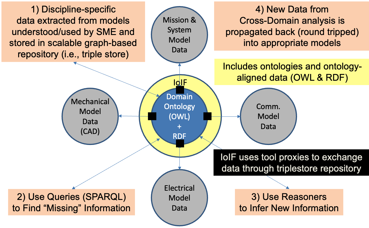
Application Ontologies serve as the bridge between domain-specific modeling tools and the semantic web technologies used in Digital Engineering (DE) workflows. They are designed to be project-specific and align with the metamodels of DE tools to facilitate seamless data exchange and interoperability.
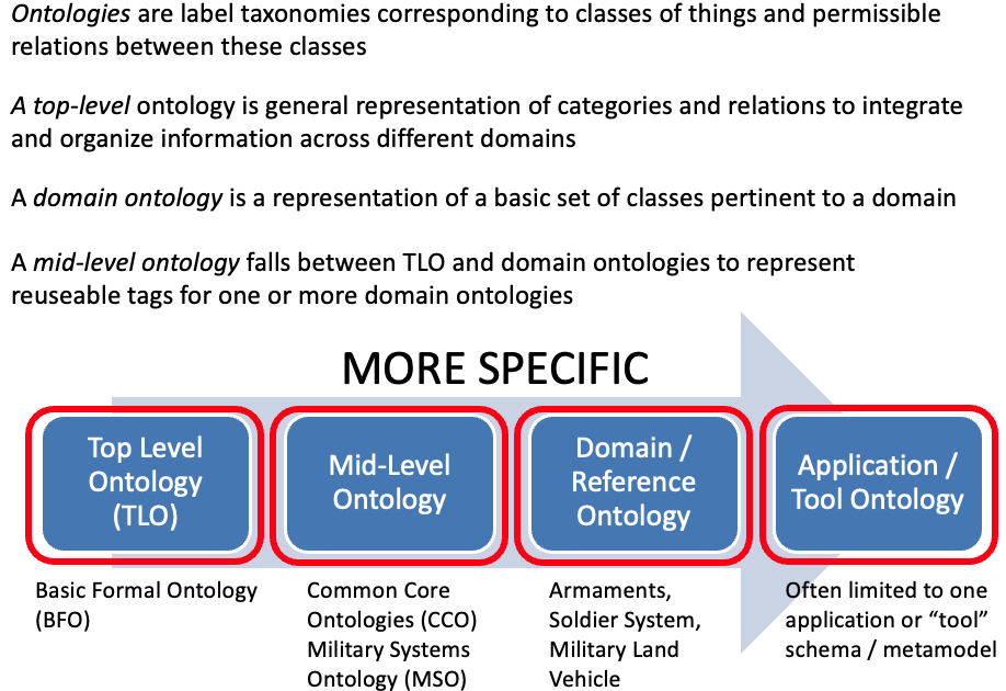
Application Ontologies are one of four main types of ontologies used in DE, alongside: - Top-level Ontologies (TLO) like BFO - Mid-level Ontologies (MLO) like CCO - Domain Ontologies (DO) that describe specific domains
Unlike Domain Ontologies, which describe "things" within a domain, Application Ontologies specifically align with the metamodels of DE tools to enable workflow integration. They define the specific data structures, relationships, and interfaces needed for a particular project or workflow.
|
Application Ontologies are the "glue" that enables different modeling tools to communicate using a common semantic framework, without requiring each tool to understand the others' internal representations. |
|
Application Ontologies are distinct from the TBox (Terminology Box) and ABox (Assertion Box), which are components of ontologies rather than types of ontologies themselves. |
Position in Knowledge Hierarchy
Broader concepts: - Ontology (is-a)
Details
Purpose and Function
Application Ontologies are created to support specific workflows and integration needs within a Digital Engineering project. They define: - The specific data structures needed for a particular workflow - The mappings between tool-specific data representations and the ontology - The interfaces for tool proxies to exchange data - The constraints and rules for data validation
Unlike Domain Ontologies that describe "what" exists in a domain (e.g., types of weapons), Application Ontologies describe "how" data flows between tools and models in a specific workflow.
Creation Process
Creating an Application Ontology involves these key steps:
Step |
Description |
Identify workflow requirements |
Determine the specific tools, data, and interactions needed for the workflow |
Define data structure |
Create classes and properties to represent the data flowing through the workflow |
Establish mappings |
Define how data from each tool maps to the ontology |
Create constraints |
Define rules for data validation using SHACL or OWL axioms |
Integrate with workflow |
Link the ontology to the workflow using tool proxies |
Relationship to Other Ontology Types
Application Ontologies build upon higher-level ontologies to provide project-specific integration:
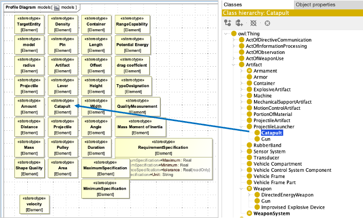
The Application Ontology: - Uses classes and relations from Domain Ontologies (e.g., Catapult, BallisticSimulation) - Leverages mid-level ontologies (e.g., Common Core Ontology) for general concepts - Aligns with the top-level ontology (BFO) for foundational philosophical principles
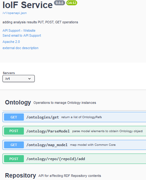
Implementation in IoIF
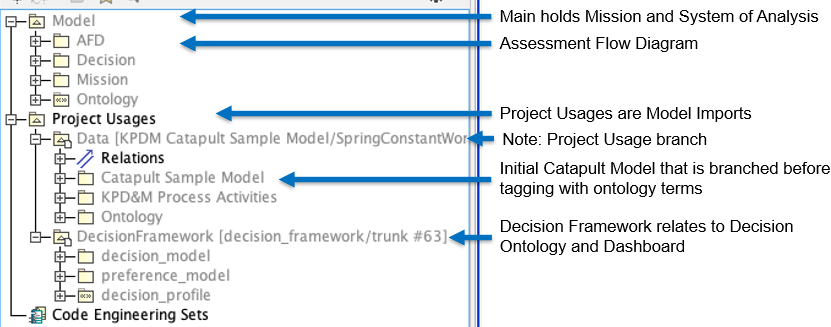
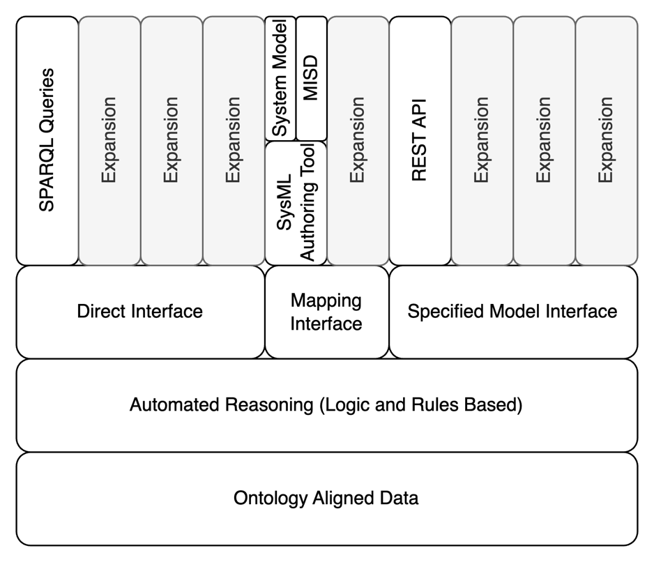
In the Armaments Interoperability and Integration Framework (IoIF), Application Ontologies are used to: - Define the data structure for the workflow - Enable the Specified Model Interface (SMI) for tool integration - Support the Assessment Flow Diagram (AFD) by providing the semantic structure for the workflow
|
Application Ontologies should be kept focused on the specific workflow they support. Trying to make them too general or comprehensive can lead to maintenance challenges and reduced interoperability. |
Practical applications and examples
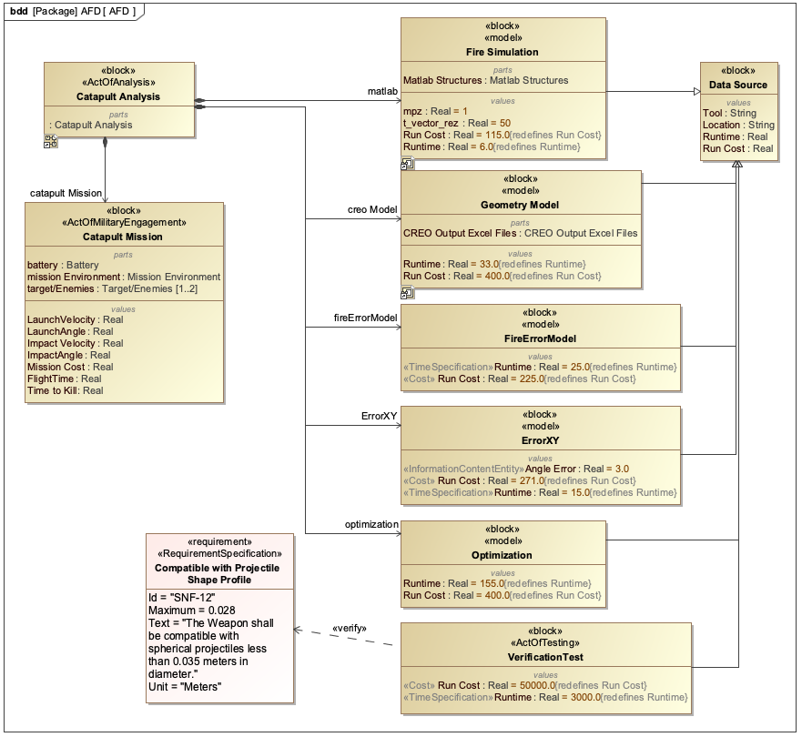
Catapult Workflow Example
The Catapult use case demonstrates how Application Ontologies enable workflow integration:
-
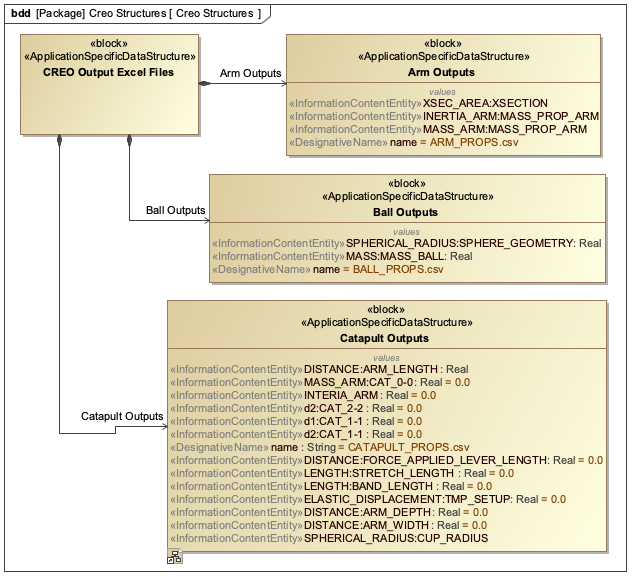
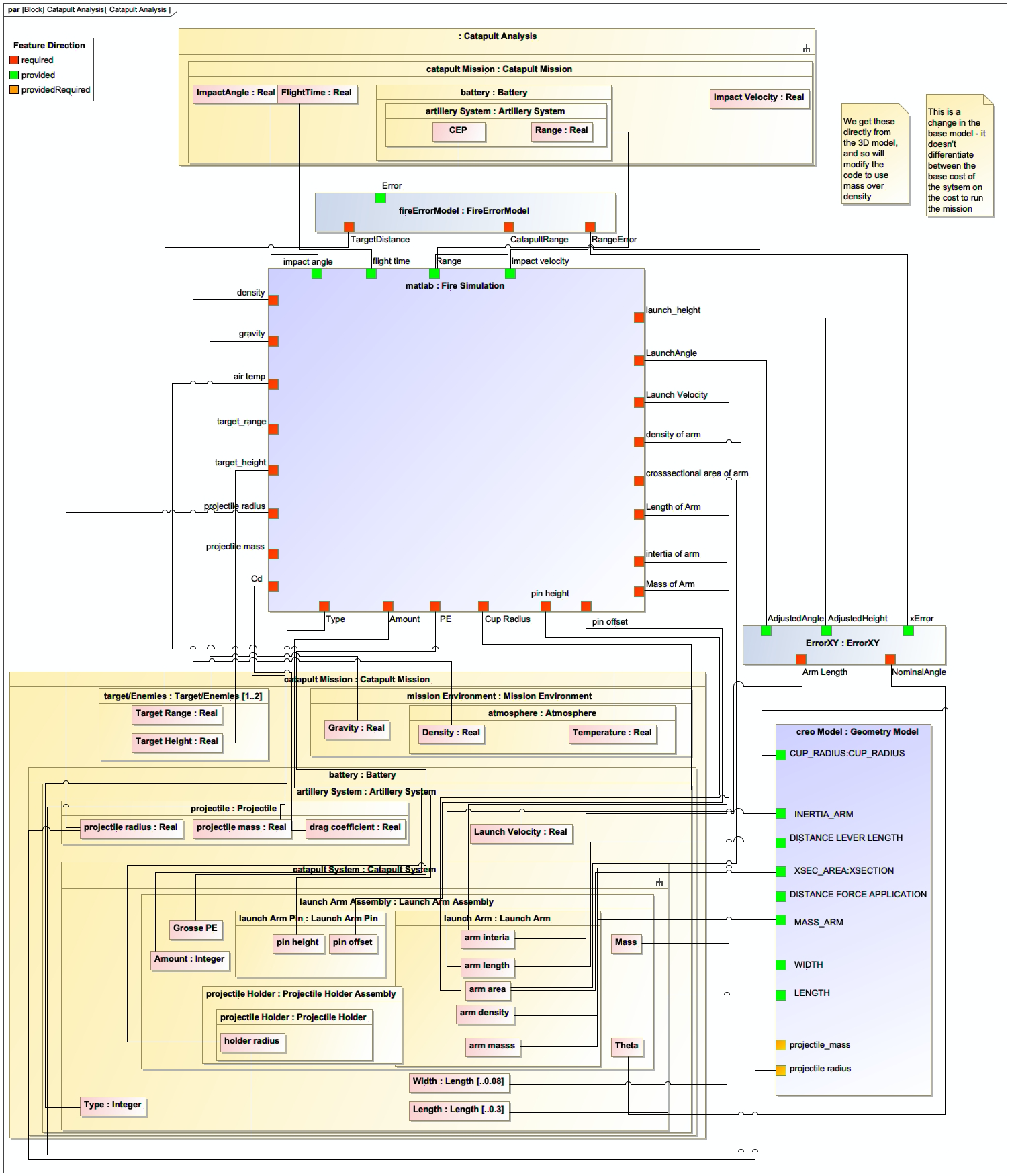
The workflow includes multiple tools: Creo (geometry modeling), MATLAB (ballistics simulation), and Python (data processing)
-
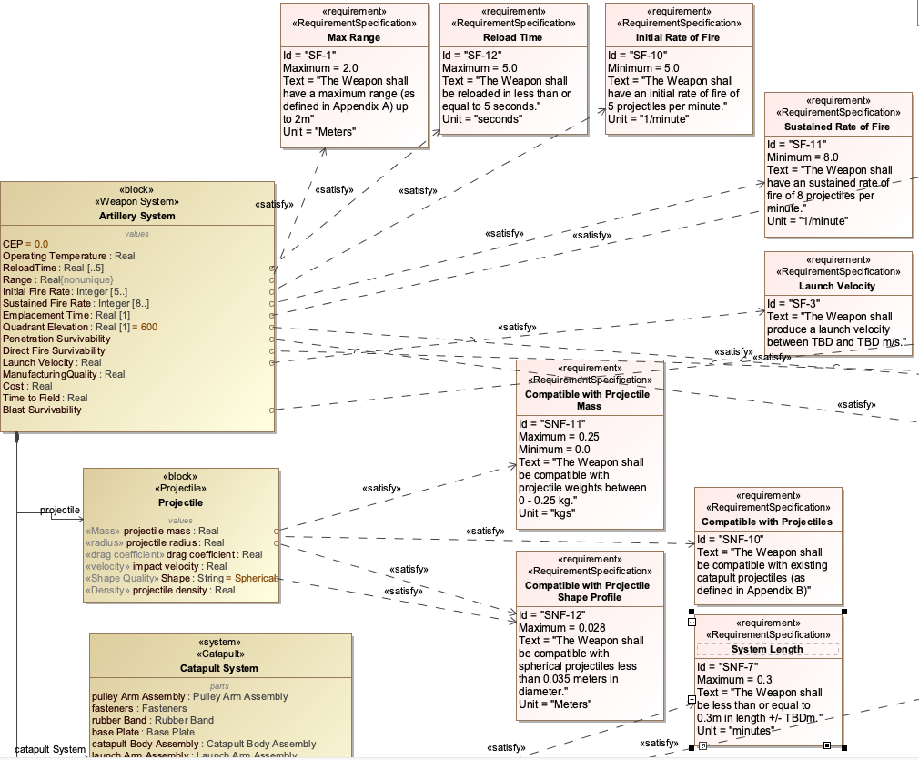
An Application Ontology defines the data structure for the catapult system and its parameters
-
Tool proxies map data from each tool to the Application Ontology
-
The workflow uses the ontology to exchange data between tools
|
The Catapult Application Ontology includes classes like Catapult, SpringConstant, Projectile, and BallisticSimulation, with properties like hasSpringConstant, hasProjectile, and hasBallisticResult. |
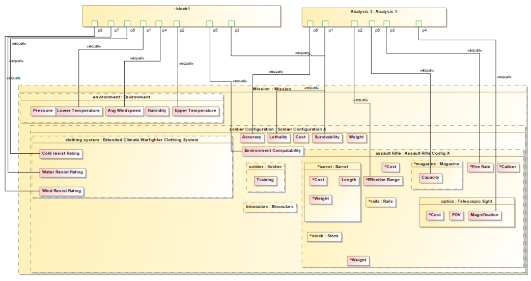
Soldier System Example
For the Soldier System case study, the Application Ontology: - Defines the specific data structure needed for soldier performance analysis - Maps from tools like simulation software to the ontology - Integrates with the Assessment Flow Diagram (AFD) to define the workflow
|
The Soldier System Application Ontology includes classes like Soldier, Clothing, and Capability, with properties like hasClothing, hasCapability, and hasPerformanceMetric. |
Workflow Integration Process
The workflow for integrating tools using an Application Ontology follows this pattern:
= Initialize IoIF with Application Ontology
ioif = IoIF(ontology="catapult_application.owl")

= Pull data from Teamwork Cloud (TWC)
system_model = ioif.pull_from_twc("catapult_model")

= Run simulation using data from ontology
ballistic_results = run_ballistic_simulation(ioif.get_data("spring_constant"))

= Store results back to ontology
ioif.store_data("ballistic_results", ballistic_results)

= Generate visualization using ontology data
dashboard = ioif.generate_dashboard("decision_dashboard")|
The Application Ontology is the central data structure that enables all data exchanges in the workflow, allowing different tools to interact through a common semantic framework. |
Related wiki pages
References
OWL 2 Web Ontology Language
Protégé Ontology Editor
SysML v2 Documentation
Basic Formal Ontology (BFO)
Common Core Ontologies (CCO)
IoIF: Driving Digital Engineering Integration and Interoperability Through Semantic Integration of Models with Ontologies
Systems Engineering for the Digital Age: Practitioner Perspectives
Shapes Constraint Language (SHACL)
Application Ontology Relationships
Visualize how Application Ontologies fit into the ontology landscape
Associated Diagrams